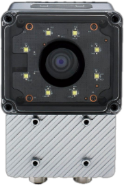
Quick Install Guide
Follow these steps to physically install and power up your OV10i / OV20i camera for the first time.
What's in the Box
 |  |  |  |  |
|---|---|---|---|---|
| OV10i / OV20i Smart Camera | Mounting Plate or Bracket (if ordered) | M12 17-Pin A-Coded Cable (Pigtail or Extension) | M12 8-Pin X-Coded to RJ45 Ethernet Cable | Terminal Block or Power Supply Adapter (optional) |
Required Tools
 |  |  |
|---|---|---|
| 4 mm Hex Key (for mounts) | Small Flathead Screwdriver (for Terminal Block wiring) | 24 V DC Power Source (minimum 1 A output) |
Electrical Connections
Confirm pinout before powering. Incorrect wiring may damage the camera. For full wiring details, see Power + M12 Wiring Guide.
The OV20i uses a 17-pin M12 A-coded connector for all power, I/O, and communication.
- Power Pins:
- Pins 13 or 14 = 24 V DC (+)
- Pins 5 or 6 = GND (−)
You can:
- Use a pigtail cable directly wired to a regulated 24 V DC power supply (minimum 1 A output).
- Or connect via a M12 to Terminal Block Base, which exposes all pins.
Mounting the Camera
It’s normal for the camera to become hot to touch when powered. For high-temperature environments, use the front mounting points.
- Use the included mounting plate/bracket or a custom rig.
- Ensure the camera is stable and secure.
- Position the camera at the working distance specified for your lens.
For CAD integration, download 3D models: Mounting Plate (STEP) | Camera Body (STEP) | Camera Body (SLDPRT)
- The OV20i uses S-mount lenses with fixed focal lengths (e.g., 12 mm, 25 mm).
- The camera includes a motorized focus for fine adjustment, but not optical zoom.
- Use lens specs to set the correct distance from the part.
For best results, avoid glare, shadows, or backlight.
Network Setup
- Connect the Ethernet port to a laptop or switch.
- Set your computer to the
192.168.0.Xsubnet to communicate.
The camera ships with:
- Static IP:
192.168.0.100 - DHCP: Off by default (can be enabled in settings)
Use the micro-USB debug port for emergency access (192.168.55.1).
Network Specifications
Overview.ai cameras (e.g., OV20i, OV80i) are industrial AI vision systems that typically meet the following network specs:
| Feature | Typical Value |
|---|---|
| Interface | 1 Gbps Ethernet |
| Protocol | TCP/IP (often with FTP/MQTT/REST/API) |
| Typical Bandwidth Usage | ~15–50 Mbps per camera (varies by image resolution, frequency, and AI model) |
| Peak Bandwidth | Can briefly spike up to 100–200 Mbps during image uploads or bursts |
Rule of Thumb (per camera):
- Minimum port speed: 1 Gbps
- Recommended per-port buffer: >100 KB to handle bursts
- Uplink/backbone capacity: If aggregating cameras to a switch, uplink should handle ~200–300 Mbps per camera (accounting for overhead)
Power-Up Check
Once powered:
- All 4 LEDs on top of the camera should light up.
- If only 3 or fewer turn on, verify voltage and pin alignment.
- Boot completes in ~30 seconds.
Ready to Go
In Chrome or Edge, open http://192.168.0.100 to access the camera's web interface.
Prefer watching over reading? Check out our video walkthroughs on the homepage for step-by-step visual guides on recipe creation, inspection setup, and integration.
🔗 See Also
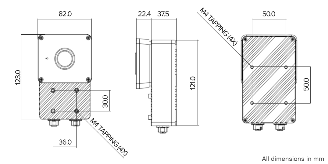
2D Drawings
OV10i/OV20i Dimensions (mm):
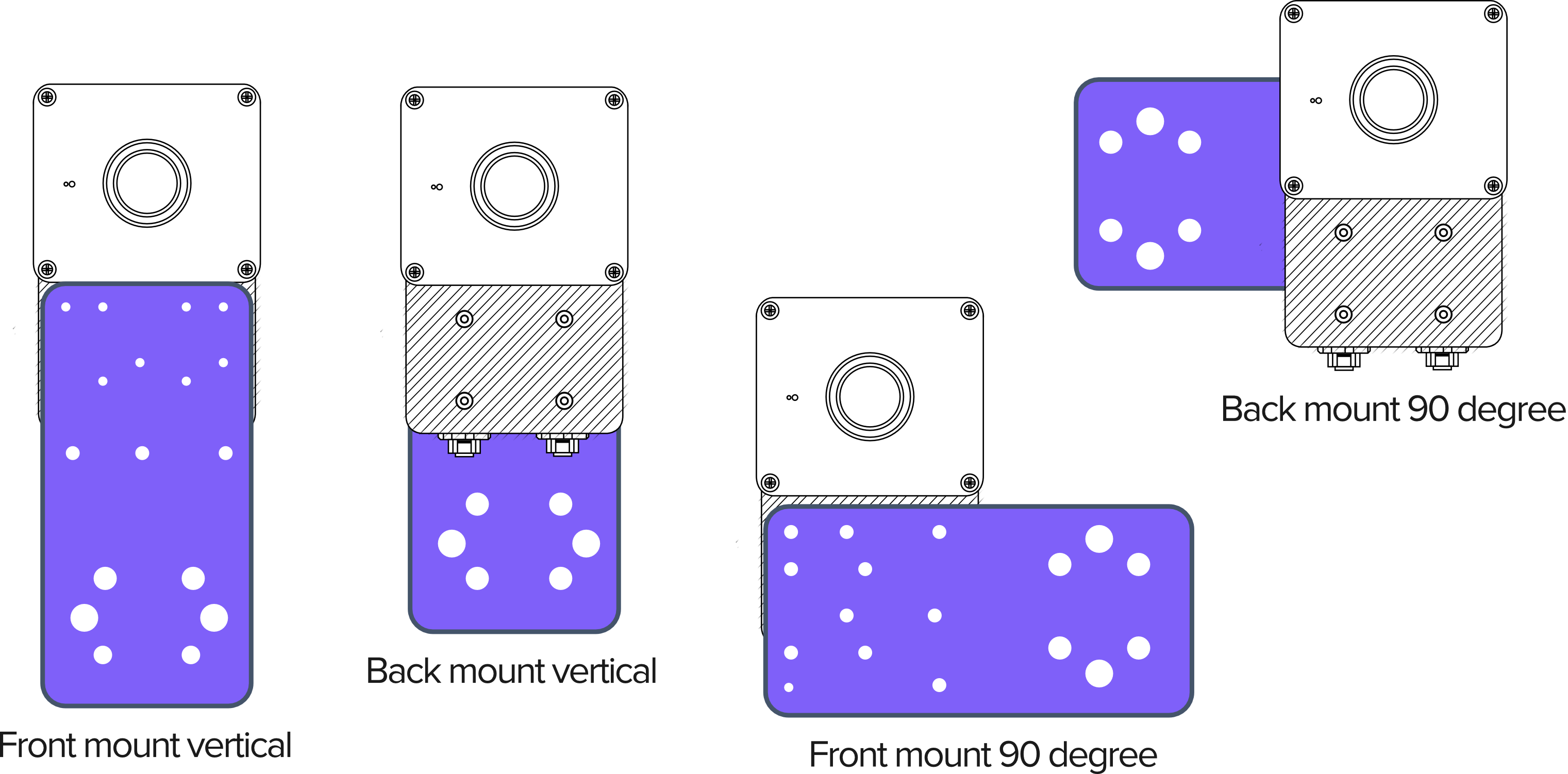
OV10i/OV20i Mounting Arrangements:
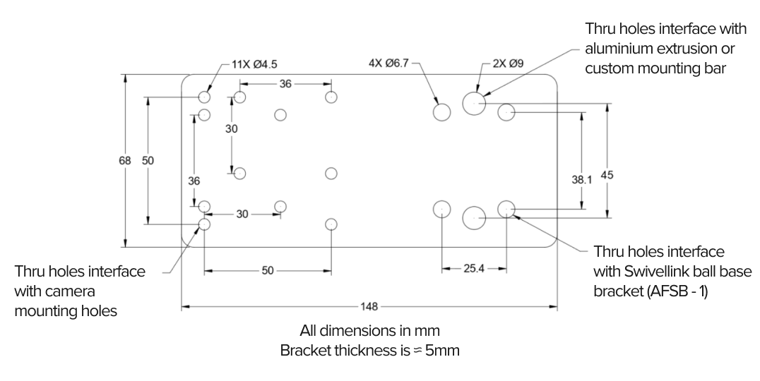
OV10i/OV20i Mounting Plate:
Download 3D Models
Download 3D CAD models for the mounting plate, bracket, and camera body for integration planning:
OV10i/OV20i: